2026 Best PEEK CF30 Material Properties Guide?
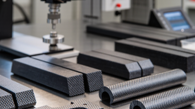
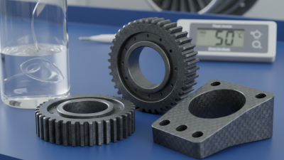
PEEK CF30 is not simply PEEK with thirty percent carbon fiber added. Its performance depends on fiber orientation, molding pressure, cooling rate, and the final part geometry. This 2026 guide examines peek cf30 material properties through an engineering lens, not a brochure headline. It connects stiffness, tensile strength, thermal stability, creep resistance, wear behavior, density, and dimensional control with real component demands.
Professor Michael F. Ashby, a leading materials-selection authority, explains the central principle clearly: “Materials are chosen for performance in context, not for a single property.” That principle matters here. A molded PEEK CF30 bracket may resist deformation along the flow direction, yet show different strength across the weld line. A dry bearing may perform smoothly, while a poorly finished shaft damages it quickly. Numbers need context.
The guide also addresses processing temperature, fiber alignment, moisture control, and post-machining effects. Small manufacturing differences can alter results. This is easy to underestimate. Supplier datasheets often report ideal laboratory values, while production parts face vibration, chemicals, heat cycling, and repeated loads. Some published comparisons also simplify anisotropic behavior too aggressively. That deserves caution.
Readers will find practical interpretation rather than isolated specifications. We will compare typical property ranges, explain test-method limitations, and identify where PEEK CF30 may outperform unreinforced PEEK or other engineering plastics. The discussion remains deliberately realistic. Material selection is rarely perfect. A stronger grade can increase brittleness, tool wear, or cost. The best choice is the one that survives the complete service environment.
PEEK CF30 Composition, Grades, and Reinforcement Structure
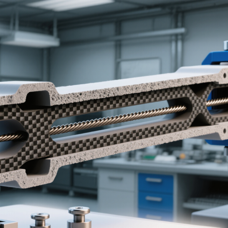
PEEK CF30 is a semi-crystalline engineering composite containing approximately 30% chopped carbon fiber by weight. The remaining structure is PEEK resin, with small formulation additives sometimes used for processing or wear control. Carbon fibers create a stiff internal skeleton, while the polymer phase supplies chemical resistance and continuous temperature performance. The architecture is directional, so molded parts usually perform better along the fiber-flow direction.
Published ISO 527 test reports and CAMPUS material records commonly place tensile strength near 200–240 MPa and tensile modulus around 14–18 GPa. Density often measures about 1.45–1.55 g/cm³.
These values are useful, but not universal. Fiber length, crystallinity, moisture history, and molding pressure can shift results noticeably. A data sheet is not a guarantee.
Grade selection depends on the reinforcement structure and service demand. Standard CF30 grades suit rigid housings, structural clips, and wear components. Bearing-focused grades may add solid lubricants, reducing friction but sometimes lowering strength. Unfilled PEEK offers greater ductility, while glass-fiber grades provide different stiffness and dimensional behavior.
ISO 527, ISO 178, ISO 75, and ASTM D638 reports should be reviewed together, not selectively.
In practical testing, poorly packed fibers can leave visible flow lines and weaker weld regions. That detail is easy to overlook. Temperature cycling also deserves attention, because laboratory strength may not represent long-term performance near 250°C.
Key Mechanical, Thermal, Chemical, and Electrical Properties
2026 Best PEEK CF30 Material Properties Guide
PEEK CF30 combines a PEEK matrix with about 30% chopped carbon fiber. ISO 527 test reports commonly show tensile strengths near 180–230 MPa and tensile moduli around 16–20 GPa. ISO 178 data often places flexural strength above 250 MPa. Fiber direction matters greatly. Mold flow can make one sample outperform another.
Thermal performance remains a major advantage. ASTM D648 reports often show heat deflection temperatures near 280–300°C under elevated load. PEEK melts near 343°C, while continuous service is commonly specified near 250°C. Actual limits depend on stress, oxygen, and exposure time. The numbers are not absolute.
Chemically, PEEK CF30 resists oils, fuels, solvents, and many acids. Strong oxidizers and concentrated acids require separate testing. Carbon fiber also reduces electrical insulation compared with unfilled PEEK. Published electrical datasets report volume resistivity varying from roughly 10⁵ to 10⁹ Ω·cm, depending on fiber sizing, moisture, and processing. That range is wide. It deserves more attention than many design guides provide. ISO 11357 thermal testing and ASTM E831 expansion data also show lower thermal expansion, often near 20–35 µm/m·K along the flow direction. Across the fiber direction, expansion can rise noticeably. I would verify every value on the final molded geometry.
Manufacturing Methods and Processing Requirements for PEEK CF30
PEEK CF30 combines a PEEK matrix with approximately 30% carbon fiber reinforcement. Published datasets in the CAMPUS plastics database commonly report tensile strength near 150–200 MPa and tensile modulus around 18–25 GPa. Actual values depend on fiber alignment, moisture control, and test direction. The material usually retains useful performance near 250°C in continuous service, although design limits should follow validated ISO 527 and ISO 178 testing.
Manufacturing starts with drying. Many processing guides recommend drying pellets at about 150°C for three to four hours, especially after open storage. Injection molding often requires melt temperatures between 370°C and 400°C. Mold temperatures may reach 160–200°C to improve crystallization and reduce internal stress. Keep the flow path short. Carbon fiber increases wear on screws, gates, and check rings. Machining is also practical, but sharp carbide tools and controlled feeds are essential. I would not trust generic PEEK settings without trial parts.
Tips: Measure moisture before molding, then record barrel temperature, mold temperature, pressure, and cooling time. Use ASTM or ISO test samples from the same production lot. Fiber orientation can create surprising strength differences. Regrind needs caution; repeated heat history may reduce consistency. A small process window is often safer than chasing maximum speed.
Material Selection, Design Factors, and Quality Evaluation Criteria
2026 Best PEEK CF30 Material Properties Guide?
Material Selection, Design Factors, and Quality Evaluation Criteria
PEEK CF30 contains about 30% carbon fiber, improving stiffness, strength, and dimensional stability. It suits bearings, seals, structural supports, and high-temperature components. Select it by checking load, temperature, chemical exposure, and sliding speed together. A material that performs well in a dry test may creep under continuous load. That difference matters.
Practical design reviews often uncover avoidable problems. Carbon fibers can create directional strength differences during molding. Aligning the main load with fiber flow may improve performance, while poor gate placement can weaken a thin section. Allow clearance for thermal expansion and machining variation. Avoid sharp internal corners. They concentrate stress. Carbon fiber also increases electrical conductivity, so it may not suit insulation requirements. In some designs, the stiffness advantage is overstated because the mounting structure remains flexible.
Quality evaluation should combine supplier documentation with independent inspection. Confirm resin identity, carbon fiber content, density, and batch traceability. Tensile, flexural, compression, and wear tests should follow recognized methods and match the actual service temperature. Differential scanning calorimetry can verify melting behavior and processing history. Microscopic inspection may reveal voids, fiber bundles, or poor dispersion. Measure critical dimensions after conditioning, not immediately after machining. That step is easy to miss. Reject vague certificates that provide only typical values without test conditions. A careful specification should define acceptance limits, sampling frequency, surface defects, and retest procedures. Even then, real component testing remains valuable because published properties rarely capture every design interaction.