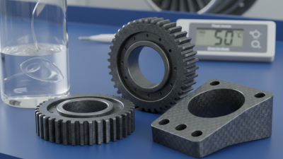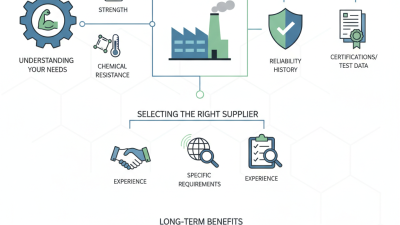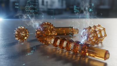
China’s PEEK CF30 market deserves careful attention because “30% carbon fiber” does not describe every performance result. It indicates a reinforced PEEK grade containing approximately 30% carbon fiber by weight. The actual peek cf30 material properties depend on resin quality, fiber length, molding direction, processing temperature, and supplier formulation. Small differences can change the result.
Dr. Jürgen Karger-Kocsis, a respected polymer-composites researcher, emphasized a practical principle: “Composite performance depends on the interaction between the matrix and the reinforcement.” That idea remains useful here. Carbon fiber can greatly improve stiffness, tensile strength, dimensional stability, and creep resistance. It can also reduce thermal expansion. However, the material may become more anisotropic after injection molding. A test bar can perform strongly along the flow direction, then behave differently across it.
This guide explains China-sourced PEEK CF30 through engineering details, not marketing claims. It examines tensile properties, flexural modulus, wear behavior, temperature resistance, density, electrical response, and chemical durability. It also considers surface finish and mold design. These details matter when a component must survive repeated heat cycles or dry sliding contact.
The numbers still need caution. Datasheets may use different test standards, conditioning methods, and specimen directions. A quoted value is not a universal guarantee. Real parts can surprise you.
For reliable selection, compare certificates, test methods, batch data, and application-specific samples. PEEK CF30 can be an excellent choice, but only when its measured behavior matches the operating conditions.
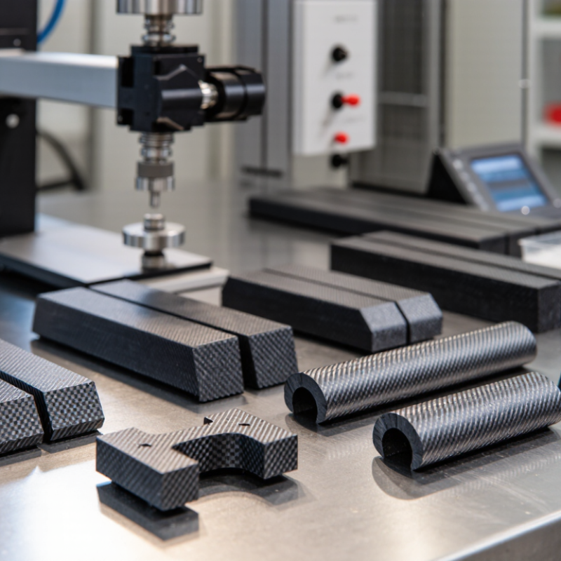
PEEK CF30 is a high-performance engineering material made from PEEK resin reinforced with about 30% carbon fiber. The fibers improve stiffness, dimensional stability, and resistance to creep under constant load. This matters when a component must hold its shape near heat, friction, or aggressive chemicals. In practical testing, a machined CF30 part often feels noticeably more rigid than unfilled PEEK.
In China, PEEK CF30 is used for demanding components in industrial equipment, medical instruments, electrical systems, and transportation applications. Local manufacturers value its strength-to-weight ratio and its ability to reduce metal replacement weight. It can also support dry-running designs, where adding conventional oil is difficult or undesirable. A dark, finely textured surface is common after machining. The material is not selected for appearance.
Processing requires care. Carbon fiber can increase tool wear, affect surface finish, and create directional differences in strength. Molding temperature, cooling speed, and fiber orientation all influence the final result. Engineers should confirm data through application testing rather than rely on a catalog value alone. That step is sometimes underestimated. PEEK CF30 is powerful, but it is not a universal solution; poor design, moisture control, or inaccurate tolerances can still cause failure.
| Property or Dimension | Typical PEEK CF30 Information | Why It Matters in Engineering Applications |
|---|---|---|
| Material Definition | PEEK reinforced with approximately 30% carbon fiber by weight | Carbon fiber reinforcement increases stiffness, strength, dimensional stability, and wear performance compared with unfilled PEEK. |
| Base Polymer | Polyether ether ketone, a high-performance semi-crystalline thermoplastic | The polymer provides high-temperature capability, chemical resistance, low moisture absorption, and good resistance to hydrolysis. |
| Density | Approximately 1.40–1.45 g/cm³ | The material offers a relatively low density compared with many metals while maintaining high specific strength and stiffness. |
| Tensile Strength | Typically about 150–220 MPa, depending on grade, processing, and test direction | High tensile strength supports load-bearing components, structural insulators, seals, guides, and precision mechanical parts. |
| Tensile Modulus | Typically about 12–18 GPa | The increased modulus helps reduce deformation under load and improves dimensional control in demanding assemblies. |
| Elongation at Break | Commonly about 1.5–3% | Carbon fiber makes the material stiffer but less ductile than unreinforced PEEK, so component geometry and stress concentration must be considered. |
| Continuous Service Temperature | Often suitable for approximately 250–260°C in air when properly designed | High-temperature capability enables use near engines, pumps, chemical equipment, electrical systems, and other heat-intensive assemblies. |
| Melting Temperature | Approximately 343°C | Processing equipment must provide accurate high-temperature control, suitable tooling, and adequate mold-temperature management. |
| Glass Transition Temperature | Approximately 143°C | Above this transition range, stiffness can decrease; operating conditions should therefore be evaluated together with mechanical loading. |
| Water Absorption | Low; commonly around 0.1–0.3% after standard conditioning | Low moisture uptake helps maintain electrical, dimensional, and mechanical performance in humid environments. |
| Coefficient of Linear Thermal Expansion | Typically around 15–30 × 10−6/K, depending on fiber orientation | Carbon fiber reduces thermal expansion, improving dimensional stability; molded parts may still show anisotropy caused by fiber flow direction. |
| Wear and Friction Behavior | Generally better wear resistance and lower thermal expansion than unfilled PEEK | Suitable for bearings, wear rings, thrust washers, seals, and sliding components, especially when paired with an appropriate counterface and lubrication condition. |
| Chemical Resistance | Strong resistance to many hydrocarbons, fuels, oils, solvents, and process chemicals | Supports use in chemical processing, fluid handling, energy, transportation, and industrial equipment. Compatibility should be verified for concentrated acids, bases, and high-temperature exposure. |
| Electrical Performance | Lower electrical insulation than unfilled PEEK because carbon fiber is electrically conductive | Useful for antistatic or conductivity-related applications, but it is not the preferred choice when high dielectric insulation is required. |
| Flame Behavior | PEEK has inherently strong flame resistance and low smoke characteristics; exact ratings depend on thickness and formulation | Can support demanding transportation, electrical, and industrial applications, subject to project-specific testing and regulatory requirements. |
| Dimensional Stability | High, with improved creep resistance compared with unreinforced PEEK | Helps maintain tolerances in precision parts exposed to continuous load, elevated temperature, or repeated thermal cycles. |
| Processing Methods | Injection molding, compression molding, extrusion, and machining from semi-finished stock | Processing requires careful drying, high melt temperature, suitable mold heating, and control of fiber orientation to achieve consistent results. |
| Common Applications | Bearings, bushings, gears, seals, valve components, pump parts, electrical components, and lightweight structural parts | The combination of strength, temperature resistance, chemical resistance, and low wear makes PEEK CF30 suitable for metal replacement and high-performance polymer components. |
| Why It Is Used in China | Demand is supported by industrial automation, transportation, energy, electronics, medical equipment, chemical processing, and advanced manufacturing | PEEK CF30 can reduce component weight, improve corrosion resistance, simplify part integration, and support locally manufactured high-performance components. |
| Key Design Considerations | Fiber orientation, weld lines, shrinkage, surface finish, notch sensitivity, operating temperature, and counterface compatibility | Published property values are not universal. Final performance depends on formulation, molding conditions, specimen direction, part geometry, and the applicable test standard. |
Note: The values shown are typical engineering ranges for 30% carbon-fiber-reinforced PEEK and are provided for material comparison and preliminary design. Exact properties should be confirmed using the technical data sheet and test method for the selected non-branded material grade.