Huntersville, NC: (704) 992-8100     Putnam, CT: (860) 928-7911

How to Choose Carbon Reinforced PEEK in 2026?

In 2026, choosing carbon reinforced peek requires more than comparing tensile strength numbers. The right grade must match temperature, load, wear, chemical exposure, and manufacturing method. A valve seat may need dimensional stability at 200°C, while a lightweight bracket may prioritize stiffness over friction. Small differences matter. Carbon content, fiber length, orientation, and molding history can change performance. This article introduces a practical framework for making that choice with fewer assumptions.

Reliable selection begins with verified evidence. Review the technical data sheet, processing guidance, lot traceability, and independent test conditions. Ask whether values were measured dry, after conditioning, or at elevated temperature. Check tensile modulus, compressive strength, creep, fatigue, thermal expansion, and wear behavior. Do not treat one impressive graph as a guarantee. Experienced engineers also inspect machining allowances, surface finish, and anisotropy before approving a design. A supplier’s application history can help, but it should support testing rather than replace it.

The final decision should balance performance, cost, availability, and risk. Prototype the actual geometry, especially around holes, thin walls, and sliding interfaces. Measure parts after realistic heat, pressure, and chemical exposure. Some recommendations will remain uncertain. That is normal. A grade that performs well in a laboratory coupon may disappoint in production. Document the reason for every choice, including rejected alternatives. With transparent data and controlled validation, carbon reinforced peek can deliver durable, predictable components in demanding equipment. Yet material selection is never finished at the datasheet; field feedback should refine it.
How to Choose Carbon Reinforced PEEK in 2026?

Understanding Carbon-Reinforced PEEK and Its Main Variants

How to Choose Carbon Reinforced PEEK in 2026?

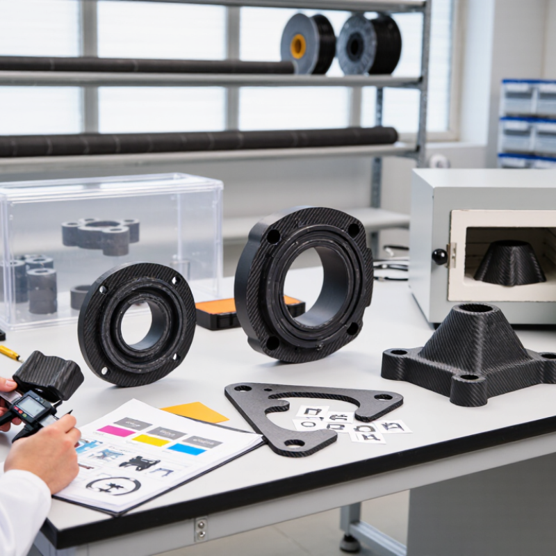
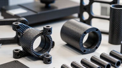
Carbon-reinforced PEEK usually means PEEK filled with carbon fiber, not carbon black. The main variant is short carbon-fiber PEEK, commonly containing 10%, 20%, or 30% fiber by weight. It suits injection molding, bearing cages, seals, and precision guides. Carbon fiber raises stiffness and reduces thermal expansion. It can also increase tool wear and create directional strength.

Continuous carbon-fiber PEEK is different. It uses tapes, fabrics, or laminated layers. This structure can deliver higher specific strength in aerospace panels and structural brackets. The U.S. Department of Energy’s Lightweight Materials Annual Progress Report 2023 places carbon-fiber composites near 1.5–1.6 g/cm³, compared with steel near 7.8 g/cm³. The weight advantage is real. Processing is less simple.

A 2025 PEEK market assessment from Mordor Intelligence identifies carbon-filled grades as a distinct growth segment across industrial, electrical, and medical applications. However, market forecasts do not replace testing. I have seen designs fail after engineers copied tensile values from a dry datasheet. Moisture, fiber direction, molding pressure, and temperature changed the result. Ask for ASTM-based data, not only marketing averages. Check wear, creep, surface finish, and electrical conductivity for the actual geometry. Black is not a specification.
How to Choose Carbon-Reinforced PEEK in 2026?

Representative comparison of unfilled PEEK and common carbon-fiber-reinforced PEEK variants. Increasing carbon-fiber content generally improves stiffness, while density also increases.

Typical midpoint values based on commonly published engineering data for injection-molded PEEK compounds. Actual performance depends on fiber orientation, processing conditions, fiber length, temperature, and test method. Choose lower reinforcement for improved toughness and dimensional stability, and higher reinforcement for maximum stiffness and load-bearing performance.

Identifying Performance Requirements for Your Application

How to Choose Carbon Reinforced PEEK in 2026?

Identifying Performance Requirements for Your Application

Start with the load, temperature, chemicals, and service life. Do not select carbon reinforced PEEK from tensile strength alone. A component inside a dry, heated chamber needs different properties from a sliding seal exposed to oil. Define peak temperature, continuous temperature, contact pressure, movement speed, and cleaning chemicals. Small details matter.

Industry data helps set realistic targets. The 2024 MarketsandMarkets analysis identifies aerospace, automotive, and electrical applications as major growth areas for carbon-fiber-reinforced polymers. ASTM D638 testing commonly shows carbon-filled PEEK compounds reaching tensile moduli above 10 GPa, depending on fiber content and orientation. This stiffness can reduce deflection, but it may also increase brittleness and mold-flow sensitivity. Stronger is not always better.

Check wear, friction, dimensional stability, and electrical behavior under actual conditions. Use ASTM D638 for tensile testing, ASTM D648 for heat deflection, and ASTM D4060 for comparative abrasion screening. Test molded parts, not only polished laboratory specimens. Fiber alignment can create different results along and across the flow direction. I have seen designs fail because engineers trusted a catalog value without measuring the finished geometry. That mistake is easy to repeat. Build a small test plan, include humidity and thermal cycling, and question any result that looks unusually perfect.

Comparing Fiber Content, Strength, Stiffness, and Wear Resistance

How to Choose Carbon Reinforced PEEK in 2026?

Carbon fiber content strongly influences reinforced PEEK performance. Grades with 10% fiber often balance toughness, stiffness, and processability. Around 20% usually delivers higher tensile strength and dimensional stability. A 30% formulation can provide exceptional stiffness, but it may become less forgiving under impact or sharp stress concentrations.

Fiber direction matters greatly. Injection molding can align fibers along the flow path, creating uneven strength across the component. Design engineers should inspect both flow and transverse test data, rather than trusting one headline value. Short fibers also increase shrinkage differences and may complicate tight-tolerance parts. Real parts rarely behave exactly like test bars.

Wear resistance requires a wider assessment. Carbon reinforcement can reduce deformation under load and improve sliding durability. However, performance depends on contact pressure, speed, temperature, surface finish, and the opposing material. In practical trials, a polished shaft may produce very different results from a rough counterface. Test under the actual load cycle. Dry running can expose weaknesses quickly.

Review tensile strength, flexural modulus, fatigue behavior, and coefficient of friction together. Higher stiffness is not always better. A rigid part can transfer stress into fasteners or mating surfaces. Reliable selection combines certified material data, processing records, and application-specific testing. Small design assumptions can become expensive failures.

Evaluating Processing Methods, Compatibility, and Long-Term Stability

How to Choose Carbon Reinforced PEEK in 2026?

Carbon reinforced PEEK selection starts with the processing method, not the material label. Injection molding needs stable melt flow, controlled drying, and a mold temperature suited to crystallization. Many grades process near 360–400°C, but exact settings vary with fiber content and geometry. Small changes can affect weld lines, shrinkage, and surface quality. Do not trust one trial.

Compression molding may suit thick plates or low-volume parts. It usually offers fewer flow-related defects, yet cycle times can increase. During production checks, examine fiber orientation near gates, corners, and drilled holes. These areas often show uneven stiffness or premature cracking. A polished sample can hide this weakness.

Compatibility requires more than chemical resistance. Check contact with oils, cleaning fluids, metals, seals, and nearby polymers at real temperatures. Carbon fibers can improve stiffness and wear resistance, but they may increase electrical conductivity and tool abrasion. Long-term stability should include creep, fatigue, thermal cycling, and moisture exposure. Test assembled parts, not only flat plaques. A six-month test may still miss ten-year behavior. That limitation deserves honest documentation. Engineers should compare measured retention after aging, then review whether the safety margin remains practical for the actual load, temperature, and processing history.

Selecting the Right Carbon-Reinforced PEEK Grade in 2026

Selecting the right carbon-reinforced PEEK grade in 2026 starts with the load, temperature, and production method. MarketsandMarkets’ 2024 analysis estimated the global PEEK market at about USD 1.1 billion in 2023, with strong growth expected through 2028. Its figures vary from other studies. That difference matters. Market forecasts are not design specifications.

For a rigid housing, a 30% carbon-fiber PEEK grade often offers tensile modulus near 18–22 GPa. It can also reduce thermal expansion and improve dimensional stability. For sliding parts, choose a grade with tested wear performance, not simply the highest carbon content. ASTM D638 tensile data and ASTM D790 flexural data provide useful comparisons. Ask for results at the actual service temperature. Room-temperature values can mislead.

Processing experience is equally important. Injection molding may create fiber orientation, making one axis stiffer than another. A machined component may behave differently from a molded component. Check moisture conditioning, thermal cycling, and batch-to-batch variation. ISO 527 and ISO 178 testing can support supplier comparisons. I would not select a grade from a datasheet alone. The overlooked detail is often surface finish. It can change friction, sealing, and fatigue life. Test the real geometry. That step costs time, but skipping it can cost more.

How to Choose Carbon Reinforced PEEK in 2026? – Selecting the Right Carbon-Reinforced PEEK Grade in 2026
Grade Family Typical Carbon-Fiber Content Density
(g/cm³)
Tensile Strength
(MPa)
Tensile Modulus
(GPa)
Elongation at Break
(%)
Continuous Service Temperature
(°C)
Dimensional Stability Electrical Behavior Best-Fit Applications
Unfilled PEEK Reference 0% 1.30–1.32 90–105 3.5–4.2 15–30 240–260 Good; higher thermal expansion than carbon-filled grades Generally electrically insulating Applications requiring toughness, chemical resistance, and electrical insulation
Light Carbon Reinforcement Approximately 10% 1.36–1.41 105–135 5.5–8.0 3–8 240–260 Improved stiffness and lower thermal expansion than unfilled PEEK Usually dissipative or semiconductive, depending on formulation Lightweight structural parts, precision components, and moderate-load bushings
Medium Carbon Reinforcement Approximately 20% 1.42–1.48 125–165 8.0–12.0 2–5 240–260 Very good; suitable for tighter thermal-expansion control Typically electrically dissipative; resistance varies by grade and processing Load-bearing housings, wear rings, rollers, pump components, and structural fixtures
High Carbon Reinforcement Approximately 30% 1.48–1.56 145–200 11.0–18.0 1.5–4 240–260 Excellent in the fiber direction; anisotropy and warpage risk increase Generally conductive or strongly dissipative High-stiffness structural parts, high-load bearings, gears, and dimensional-control components
Selection note: The property ranges above are representative engineering ranges for injection-molded carbon-fiber-reinforced PEEK and are not guaranteed material specifications. Actual values depend on carbon-fiber length, fiber orientation, molding conditions, specimen geometry, moisture history, and the applicable test standard. Use the supplier’s certified datasheet for final design validation.