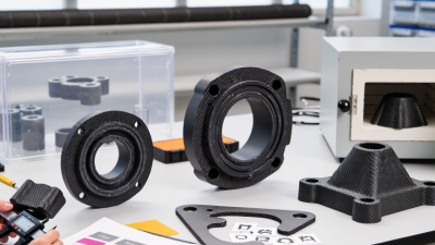
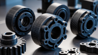
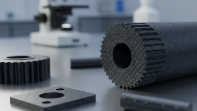
Carbon reinforced PEEK combines a high-performance thermoplastic with carbon fibers. The result is a stiff, strong, lightweight material suited to demanding components. It can resist heat, chemicals, and repeated wear, depending on the grade and operating conditions. That matters.
In a pump, a machined carbon reinforced PEEK bearing may help reduce weight and maintain dimensional stability. Similar grades are used for gears, seals, and other moving parts. Aerospace and automotive designers may consider them for lightweight structural or electrical components. But the material is not a universal upgrade. Fiber direction can affect strength, and the fibers may increase wear on a softer mating surface. Not everywhere.
Choosing a grade requires more than comparing strength figures. Temperature, load, chemical exposure, manufacturing method, and contact with other materials all shape performance. Medical applications need particular care: a standard industrial grade is not automatically suitable for implants or prolonged bodily contact. The details matter. This guide explains common uses, key benefits, and practical limits of carbon reinforced PEEK. It also considers when another material may be the more sensible choice. A careful selection process can prevent costly redesigns, though real operating conditions may still reveal surprises. No material is perfect.
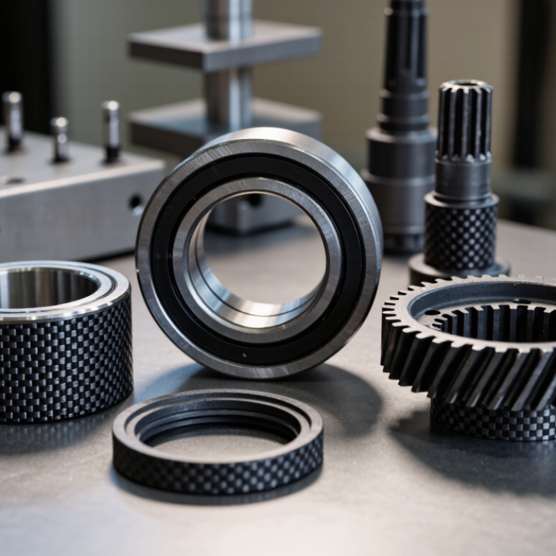
Carbon-reinforced PEEK is a high-performance thermoplastic composite. Its PEEK polymer forms the base, while short or continuous carbon fibers reinforce it. The fibers are embedded in the polymer, not simply applied as a surface coating. That matters. The result can be stiffer and more resistant to wear than unreinforced PEEK, though exact properties depend on fiber content, length, and alignment.
The material is used in components that need low weight and strength, such as industrial gears, brackets, and wear parts. Some grades suit demanding environments, but “carbon-reinforced PEEK” is not a complete specification. Fiber direction can affect strength, and a poorly chosen grade may not perform as expected. I’d check the supplier’s technical data and test the part under its actual temperature, load, and friction conditions. A datasheet alone can miss the real-world details.
Tips: Check whether the grade uses chopped or continuous fibers. Confirm its operating-temperature and wear data, then consider how the part will be machined. Carbon fibers can make machining more abrasive, so tool choice and finish deserve attention. Not quite plug-and-play.
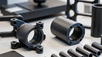
Carbon-reinforced PEEK is useful when a component must stay stiff under heat, repeated loading, or chemical exposure. Its appeal starts with the PEEK matrix: published engineering datasheets place its glass-transition temperature near 143°C and melting point near 343°C, measured using methods such as ISO 11357-2. Heat resistance is not the whole story. The carbon fibers carry load and limit deformation.
ISO 527-based material datasheets commonly report tensile moduli around 18–25 GPa for 30% carbon-fiber PEEK, compared with roughly 3.5–4 GPa for unfilled PEEK. Exact results vary with fiber length, molding direction, and test conditions. A thin bracket may feel exceptionally rigid along the flow direction, yet weaker across it. That detail matters.
Low weight and wear resistance also help in aerospace fittings, industrial pump parts, and precision machine components. PEEK tolerates many fuels, oils, and cleaning chemicals, while the fibers improve dimensional stability. It is not automatically the best choice. Carbon fibers can abrade mating surfaces, and the material costs more than many engineering plastics. Designers should check the specific grade’s datasheet and test the finished geometry; coupon values do not always predict a molded part. That gap is easy to underestimate.
Aerospace manufacturers use carbon-reinforced PEEK in clips, brackets, and other parts near warm engine or cabin systems. Its carbon fibers improve stiffness and reduce expansion compared with unfilled PEEK. Weight matters. Engineers still check fatigue, temperature, and fluid exposure for each component; a lighter part is not automatically a safer one.
In automotive and industrial equipment, the material can suit gears, bearing cages, and pump components that face repeated movement. Carbon reinforcement can improve wear behavior and dimensional stability, while PEEK tolerates demanding service temperatures. Heat is real. Design teams must consider mating surfaces and lubrication, since abrasive wear or poor alignment can shorten a part’s life. Oil and gas equipment may use selected grades for seals and backup rings, but chemical compatibility needs testing.
Medical device makers use specific carbon-fiber PEEK grades for certain spinal and orthopedic implants. The material’s imaging characteristics can help clinicians assess surrounding bone, though the exact result depends on the design and imaging method. Not every grade. Processing, cleanliness, and documented biocompatibility matter, and implant suitability requires careful validation.
Semiconductor and electronics equipment also uses precision components where low particle generation and dimensional control are important. Those benefits depend on the part’s finish and operating conditions, not the material name alone.
Carbon-reinforced PEEK is used in components that need stiffness, wear resistance, and heat tolerance without the mass of metal. Common examples include bearing cages, bushings, gears, thrust washers, and pump or compressor parts. In a bearing assembly, a small carbon-fiber-reinforced cage can guide rolling elements while facing repeated contact and lubrication changes. These parts are often machined from stock or molded, depending on shape and production volume. Details matter: fiber direction and processing can change strength and friction.
Aircraft and vehicle interiors may use lightweight structural fittings, clips, and electrical connector components made from this material. The U.S. Department of Energy’s Vehicle Technologies Office reports that a 10% reduction in vehicle weight can improve fuel economy by roughly 6–8%; that figure applies to vehicle lightweighting broadly, not specifically to carbon-reinforced PEEK. Medical devices may also use selected components, such as instrument parts, where sterilization compatibility and dimensional stability are evaluated. Not every application benefits. The material can be costly, and exposed fibers may affect a mating surface. A technical review should check temperature, load, chemical exposure, and wear conditions before specifying a grade. A neat fit is not proof of long service life.
What Is Carbon Reinforced PEEK Used For?
Factors to Consider When Selecting It
Carbon-reinforced PEEK is used in demanding parts where low weight, stiffness, and heat resistance matter. Think pump components, electrical connectors, and aircraft interior hardware. Selection starts with the actual load, not the material’s headline strength. Representative 30% carbon-fiber PEEK technical datasheets, tested under ISO 527, report tensile moduli around 18–22 GPa. Results vary by grade, fiber direction, and test conditions. Check the supplier’s exact data.
Temperature and chemical exposure need equal attention. PEEK melts near 343°C, as measured using methods such as ISO 11357 differential scanning calorimetry. That is not a safe continuous-use temperature. Review long-term thermal data, then consider the real part temperature and exposure duration. Short peaks count, too. For a wet pump housing, verify resistance to the actual fluid and inspect seals and joints; the polymer alone does not guarantee system compatibility.
Fiber alignment affects performance. Molded or machined parts may be much stiffer along one direction than another, so confirm loads against the part’s geometry. Carbon reinforcement can also increase tool wear during machining. Ask for wear and fatigue data if sliding contact or repeated loading is expected. A higher modulus can help, but it may reduce toughness. Easy to miss. Cost, tolerances, and inspection needs belong in the decision as well. Test a representative component when failure would be costly.
| Application | Why Carbon Reinforced PEEK May Be Used | Key Selection Factors | Important Limitations |
|---|---|---|---|
| Bearings and sliding components | Carbon-fiber reinforcement can increase stiffness and reduce deformation under load. It may also improve wear performance in suitable dry-running or lubricated designs. | Check contact pressure, sliding speed, operating temperature, lubrication, counterface material, surface finish, and the required service life. | Wear depends on the full tribological system. Carbon fibers can be abrasive to mating surfaces, so test the selected grade against the actual counterface. |
| Gears and other precision motion parts | The reinforcement can help limit creep and dimensional change under sustained loads, while the PEEK matrix offers a high-temperature engineering-plastic base. | Consider tooth loading, impact, noise, lubrication, allowable backlash, temperature cycling, and the direction of fiber orientation in the molded part. | Reinforcement can make a component less tolerant of impact than an unfilled polymer. Validate fatigue and wear under representative operating conditions. |
| Aerospace brackets, clips, and structural fittings | Its strength-to-weight potential, stiffness, and resistance to heat and many chemicals can suit lightweight components in demanding environments. | Review structural loads, temperature range, vibration, fire and smoke requirements, allowable mass, joining method, and applicable qualification requirements. | Material choice alone does not establish airworthiness or compliance. Use approved material data and validate the finished component and manufacturing process. |
| Automotive and industrial under-the-hood parts | The material may provide a combination of stiffness, heat resistance, and chemical resistance for components exposed to elevated temperatures or fluids. | Check continuous and peak temperatures, fluid compatibility, pressure, vibration, thermal cycling, and the required production volume and process. | Compatibility varies with fluid composition, temperature, and exposure time. Confirm performance using the actual media and component design. |
| Semiconductor and electronics equipment components | Stiffness and dimensional stability can be useful for fixtures and handling components. Carbon reinforcement can also alter electrical and thermal behavior. | Determine the required electrical resistivity, cleanliness, outgassing limits, chemical exposure, temperature stability, and surface or particle-control requirements. | Electrical properties depend on grade, fiber content, and processing. Do not assume that every carbon-reinforced grade is suitable for a particular static-control requirement. |
| Pump, valve, and fluid-handling components | The PEEK matrix is resistant to many chemicals, and reinforcement can improve stiffness for components exposed to pressure or mechanical loading. | Assess the specific fluid, concentration, pressure, temperature, sealing method, permeation needs, and applicable industry or regulatory requirements. | Chemical resistance is not universal and can change with conditions. Verify compatibility with the exact fluid, including additives and cleaning agents. |
| Oil, gas, and energy equipment parts | A high-performance polymer matrix and fiber reinforcement may be considered for components requiring stiffness and resistance to heat, pressure, or selected chemicals. | Evaluate pressure, temperature, sour-service exposure where relevant, decompression cycles, fluid compatibility, wear, and required qualification standards. | Service suitability must be established for the exact grade and conditions. Check relevant material qualifications rather than relying on general polymer properties. |
| Machined components and custom fixtures | A reinforced grade can provide greater rigidity than unfilled PEEK for parts that must retain shape under load or during repeated use. | Consider stock form, machining tolerances, tool wear, chip control, heat generation, residual stress, and the direction of reinforcement in the stock. | Carbon fibers can accelerate cutting-tool wear. Machining practices and final-part properties should be checked with the material supplier and the intended process. |
General selection note: Compare the specific grade’s datasheet and test conditions with the real operating environment. Carbon reinforcement commonly increases stiffness and can reduce creep, but may also affect impact behavior, electrical conductivity, thermal expansion, wear, and processing. Results depend on fiber content, orientation, molding or machining, and part design.