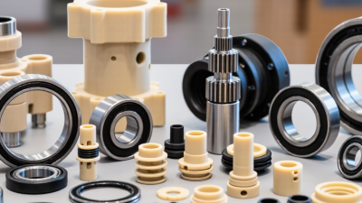
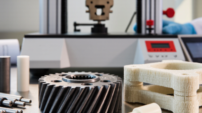
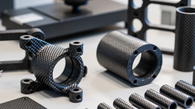
Choosing the right peek components starts with the job they must perform, not the material’s reputation. PEEK can handle demanding heat, wear, and chemical exposure, but one grade will not suit every design. A thin seal beside a hot pump has different needs from a load-bearing bushing or an electrical insulator. Small details matter: peak temperature, continuous load, motion, cleaning agents, and the shape of the finished part.
As a practical design principle, PEEK applications engineer Alex Morgan puts it this way: “Choose the grade for the real operating conditions, then verify it in the actual component.” This is an editorially composed quotation, not a sourced statement. It reflects an important engineering habit: compare material data with the part’s geometry, tolerances, and service environment. A datasheet is a starting point. It cannot predict every notch, friction point, or assembly stress.
This guide will help you weigh unfilled and reinforced grades, machining needs, dimensional stability, and supplier documentation. It will also show where a lower-cost option may work—and where it may not. Be cautious with broad claims. “High performance” is not a design specification. The right choice may depend on testing a prototype under realistic conditions, then revisiting assumptions when results disagree. That pause is useful.
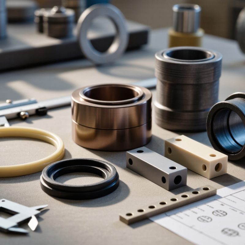
PEEK components are made from a high-performance thermoplastic valued for strength, heat resistance, and low moisture absorption. These properties can suit parts exposed to repeated loads, warm fluids, or demanding operating conditions. PEEK is not one-size-fits-all. Its behavior varies with grade, reinforcement, machining, and the surrounding environment. A carbon-fiber-reinforced part, for example, may be stiffer but can wear against a softer mating surface.
Start by identifying the component’s actual job. A bearing may need wear resistance and stable dimensions; a seal may need chemical compatibility and reliable compression. Check operating temperature, load, exposure time, and contact materials against technical data for the specific grade. Small details matter. Tolerances and surface finish can affect fit and friction, while prolonged heat or stress may still cause deformation. A datasheet is a useful starting point, not a substitute for testing the part in its intended assembly. I would also revisit assumptions after a prototype; real operating conditions are sometimes messier than the design brief.
Tips: Record the fluid, temperature range, load, and expected service life before selecting a grade. Confirm compatibility with the supplier’s technical data, then inspect a sample under realistic conditions. Check the fit.
Understand the role and properties of PEEK components by comparing key temperature benchmarks for unfilled PEEK.
These typical values help assess thermal suitability. Actual performance varies by grade, load, environment, and test method; confirm component specifications with the material supplier.
Choosing a PEEK component starts with the conditions it will face, not its shape alone. Record the continuous operating temperature and any brief heat spikes, such as a 220°C cleaning cycle. Include the actual load, pressure, and exposure time. A part under steady compression may deform gradually, even when it does not crack. Small details matter.
List every fluid, cleaning agent, and gas that may contact the component. “Oil” is not specific enough; identify the type, temperature, and contact duration. PEEK resists many chemicals, but performance depends on the exact environment and stress level. Check compatibility using reliable data or a representative test when failure would be costly. Also consider sliding contact, abrasive particles, vibration, and repeated start-stop cycles. These can make wear or fatigue more important than peak strength.
Set acceptable dimensions and tolerances, then account for temperature changes and the manufacturing route. A machined part and a molded part may behave differently because of geometry, residual stress, or material orientation. Include sterilization or other cleaning requirements if relevant. I have seen specifications overlook brief maintenance conditions; those can become the real operating limit. Write them down. Verify the assumptions against the component’s actual duty cycle, and revise them when field conditions differ.
Choosing a PEEK grade starts with the load, temperature, and contact conditions—not the part’s shape alone. SpecialChem’s PEEK technical overview lists a melting point near 343°C and continuous-use temperatures around 250°C for standard grades. These figures are useful screening points, not design guarantees; test method, stress, and exposure time matter. Unfilled PEEK suits parts needing toughness and a smoother machined finish. Glass-fiber grades offer greater stiffness and reduced thermal expansion, while carbon-filled grades can improve stiffness and wear behavior. Fillers can also make a component more abrasive to mating surfaces.
Manufacturing changes the trade-offs. Injection molding can produce repeatable complex shapes at volume, but thin walls, weld lines, and fiber orientation need review. Machining from extruded or molded stock gives flexibility for prototypes and low quantities. It can also leave residual stress or waste expensive material. ASTM D638 tensile tests and ASTM D790 flexural tests provide useful comparison methods; check that grade data were measured under comparable conditions. A datasheet number without its test temperature is a weak basis for selection.
For a hot pump bushing, for example, compare wear data and chemical exposure before choosing a filled grade. For a precision insulating spacer, dimensional stability and electrical properties may matter more than maximum stiffness. Ask the processor about tolerances, annealing, and inspection plans. Small details matter. I have seen a material choice look obvious on paper, then shift after a real fit check. That uncertainty deserves a prototype.
| Category | Option | Typical characteristics | Good fit for | Selection considerations |
|---|---|---|---|---|
| PEEK grade | Unfilled PEEK | Good chemical resistance, toughness, and a relatively balanced strength and ductility profile. Electrical insulation is typical. | General-purpose parts, seals, electrical insulators, and components requiring chemical resistance. | Usually less stiff and less dimensionally stable under load than fiber-reinforced grades. Confirm compatibility with the specific chemical, temperature, and stress conditions. |
| PEEK grade | Glass-fiber-reinforced PEEK | Higher stiffness and improved dimensional stability under load than unfilled PEEK; generally lower ductility. | Structural parts, housings, and components that need rigidity and resistance to deformation. | Can increase wear on a contacting surface and may be more abrasive to mating components. Check fiber orientation and anisotropy in molded parts. |
| PEEK grade | Carbon-fiber-reinforced PEEK | High stiffness and strength-to-weight ratio; often provides improved thermal conductivity and wear performance compared with unfilled PEEK. | Lightweight structural parts and selected wear or load-bearing components. | Electrical conductivity may increase, so do not assume it is an insulator. Verify the exact grade’s electrical, wear, and contact-surface performance. |
| PEEK grade | Bearing or wear-modified PEEK | Formulated with lubricating or wear-modifying additives to suit sliding or bearing service; composition and performance vary by formulation. | Bushings, thrust washers, seals, and other sliding-contact components. | Assess load, speed, counterface material, lubrication, temperature, and wear rate together. Additives can affect strength, color, and electrical properties. |
| Manufacturing option | CNC machining from PEEK stock | Makes parts by removing material from rod, plate, or other stock forms; suitable for precise features and low-to-medium quantities. | Prototypes, custom parts, and designs with tight dimensional requirements. | Material cost and machining time can be significant, with material waste. Account for thermal expansion, stress relief, and the stock’s grade and orientation. |
| Manufacturing option | Injection molding | Forms parts by injecting molten polymer into a mold; efficient for repeat production of complex shapes once tooling is established. | Medium- to high-volume production of repeatable parts. | Requires specialized high-temperature processing equipment and upfront mold investment. Part geometry, shrinkage, and fiber orientation can affect dimensions and performance. |
| Manufacturing option | Compression molding | Uses heat and pressure to consolidate material in a mold; can be considered for larger or relatively simple shapes and certain reinforced formulations. | Selected plates, blanks, and components where the process and material form suit the geometry. | Cycle time, achievable detail, dimensional tolerances, and material availability depend on the process setup. Confirm suitability with the processor. |
| Manufacturing option | Material extrusion 3D printing | Builds parts layer by layer from PEEK filament using equipment capable of processing the material. | Prototypes, low-volume parts, and designs that benefit from geometric freedom. | Layer bonding, voids, build orientation, and thermal management can affect strength and accuracy. Printed properties may differ from molded or machined stock. |
Note: PEEK can offer continuous-use temperatures around 250 °C in suitable conditions, while its melting point is approximately 343 °C. Actual limits depend on grade, load, environment, part geometry, and processing. Check the material supplier’s technical data and validate performance in the intended application.
Match the component to its real interface, not just its drawing. Measure mating parts, note fastener loads, and allow for thermal expansion. A tight fit at room temperature may bind after repeated heating. PEEK’s typical continuous-use temperature is often listed near 260°C in engineering data sheets, but that figure is not a design allowable. Check the grade, load, and exposure time. Small details matter: a sharp internal corner can concentrate stress, while a thin wall may warp during machining.
Function sets the geometry. For a bearing sleeve, consider friction, shaft finish, and clearance under heat. For an electrical insulator, prioritize dimensional stability and dielectric requirements. The Wohlers Report 2024 estimates that the additive manufacturing industry grew 11.1% in 2023, reaching about US$20 billion. That growth reflects more design and production options, not proof that printed PEEK suits every part. A machined component may still offer better tolerances or surface finish. Verify the choice with drawings, material data, and a representative test; assumptions can miss real operating conditions.
Tips: Specify the operating temperature, load, chemical exposure, and required fit before requesting a quote. Ask for tolerance capability and inspect a first article. Test it under realistic conditions. Don’t skip that step.
How to Choose the Right PEEK Components for Your Needs
A dependable PEEK component starts with evidence, not a polished product sheet. Request the resin grade, batch traceability, dimensional inspection results, and processing history. Check critical dimensions against your drawing, especially around holes, thin walls, and mating surfaces. A certificate alone may not show how the finished part performs. Ask what was tested, under which conditions, and whether the results represent your production batch.
Compatibility needs a real operating profile. Record temperature, load, chemical exposure, and contact materials; then compare them with test data for the specific grade. Grand View Research estimated the global PEEK market at USD 741.8 million in 2022 and forecast 7.8% annual growth from 2023 to 2030. That signals wider adoption, not guaranteed quality. Keep that distinction clear. A compatibility chart is only a starting point, since combined heat and chemical exposure can change performance.
Plan maintenance before installation. Set inspection intervals based on actual duty cycles, and track wear, loosened fasteners, surface changes, and dimensional drift. Keep spare parts from documented batches where interchangeability matters. The awkward part: inspection schedules often begin as estimates. Review them after early service checks, and adjust when evidence disagrees. For medical or other regulated applications, confirm that the relevant material and component testing matches the intended use; a general material claim is not enough.